IV-18荧光管电子钟装配指南【IV-18 Energy Pillar Assembly Instructions】

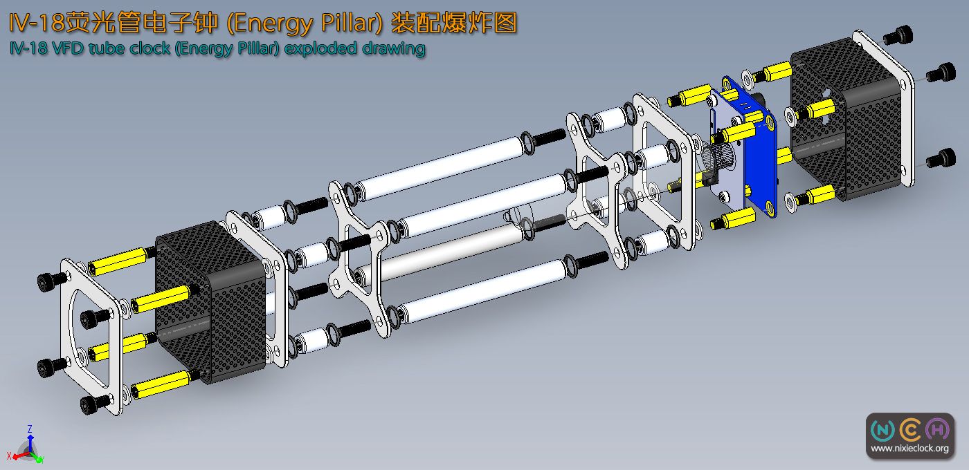
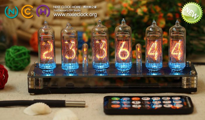
上个月推出了IV-18(ИВ-18)荧光电子管时钟DIY套件,由于外壳装配过程稍稍复杂,所以这两天用Solidworks绘制了一整套3D装配指南图片,供大家参考。
IV-18 (ИВ-18) the VFD tubes Clock DIY kit published last month, the housing assembly process is a little more complicated, so these two days with Solidworks drawn complete set of 3D assembly guide pictures for your reference.

整个外壳的装配过程请按照图示说明进行,如有疑问请大家给我留言!
The housing assembly process is carried out in accordance with the illustration, any questions please leave a message or email me!

此图高分辨率,点击此图可以放大! Click to enlarge!

此图高分辨率,点击此图可以放大! Click to enlarge!

(更多…)

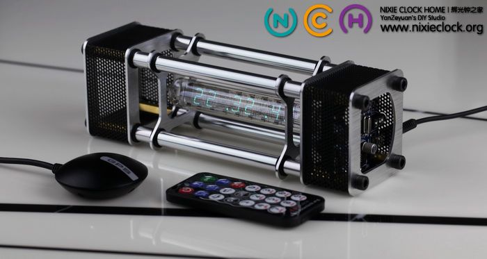
IV-18(前苏联ИВ-18)荧光管电子钟【Energy Pillar.能量柱】【严泽远作品】

一直以来,对金属质感的东西颇有些亲睐,但鉴于DIY金属外壳的难度,自从水晶城堡作品诞生以后,就没有打算在金属外壳设计上再投入大量的时间和精力。直到……

直到遇见IV-18荧光电子数码管以后,又开始了一轮新的折腾……的确,IV-18荧光管独特的外形、通透的管身,冷艳的色彩,让她与金属外壳搭配一定是完美的创作。于是,经过一次又一次的设计、修改、打样,一年多断断续续的制作,又一款电子管时钟作品诞生——Energy Pillar能量柱……


(更多…)

Adapter for IV-22 VFD Module | 荧光管显示模块转接板

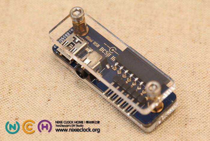
IV-22 VFD Module | 荧光管模块 设计之初就考虑到了外接电源与I、O接口的连接问题,同QS30-1辉光管显示模块一样,我也为她设计了专用的Adapter转接板。
原本,模块与模块之间均采用的是单排弯脚的8Pin排针和排母,这些针脚包括所有的控制I/O和电源接口,所以对于应用来讲,要连接电源适配器或者Arduino等控制模块需要朋友们自己动手用杜邦线连接,无法用MiniUSB线直接为模块供电,有了这个转接板,可以方便的使用DC3.5/1.35接口的直流电源或者MiniUSB接口直接为模块供电,见下图:

(更多…)

IV-22 VFD Module for Arduino [hardware design]

VFD tube, vacuum fluorescent display, which was invented in Japan in 1967, typifies the display component of the vacuum electronic era.

Just as the Nixie Tube, VFD tube is also on the verge of extinction. It has been fade out from modern applications since the 1990’s. Young generations may have never seen its limpid cyan fluorescence, given life by the intelligence of the last century.

With the same concept of developing the Nixie Tube module for Arduino, in order to make the VFD tube reborn, combined antiquated electronics with modern technology, the VFD tube module is developed as independent blocks. Without headaches about high-voltage generation, logical driver, soldering, geekers can focus their time and energy on achieving the design idea of the final works. Meanwhile, for designers with no electronic background, Arduino is all they need, of which 4 I/O pins can supply full control on a dozens of VFD tube modules with individual RGB led background lights. Other MCU systems or developer kits would do the same.

Thanks aGuegu for testing my VFD tube moudle first-handed and developmet of its Arduino library.

The technology of VFD is still widely used nowadays, however, no more in tubes. VFD screen is Hi-fi equiment, Automobile instrument panels. This device consists of a hot cathode (filaments), anodes (phosphor) and grids encased in a glass envelope under a high vacuum condition. The cathode is made up of fine tungsten wires, coated by alkaline earth metal oxides, which emit electrons when heated by an electric current. These electrons are controlled and diffused by the grids, which are made up of thin metal. If electrons impinge on the phosphor-coated plates, they fluoresce, emitting light. Constract to the Nixie tube, it requires lower supply voltage, which means is safer and longer life expectancy.

This module application use model IV-22 (ИВ-22) VFD tube, dimensioned as a rectangle of 32mm * 22mm. It display on top with 12 pins. These batch of tube were mass manufactured in former Soviet Union during the Cold War, whereas, they are stored in warehouse corners and being forgotten. But its material guarantees its unlimited shelf life.

The specifications of IV-22 VFD tube:
1.  High vacuum inside, unlike the inertia in nixie tube.
2.  Lower vlotage requirement and energy consumption. The filament voltage is between 1.0 and 1.3 volt, working both on DC and AC. The voltage of anodes (phosphor) against grids is 22-30v. The current in filament is 100mA, while 4-10mA in grids.
3.  Seven-segment digital display, can present decimal figures and basic letters.
4.  Cyan colored, bright light with high contrast, visible even in daylight, and not Glare.

Check some photos, and more description comes afterwards.
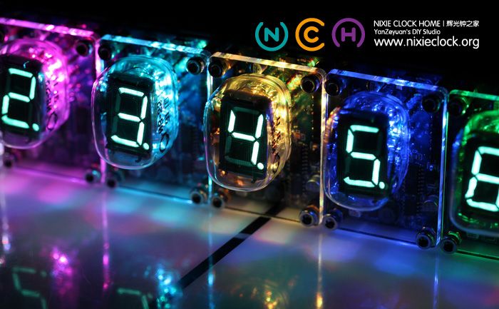
http://i1237.photobucket.com/albums/ff474/yanzeyuan/Nixie%20Module%20for%20Arduino/IV-22%20VFD%20Module/2012_12_12_IMG_8615.jpg

(更多…)

IV-22 VFD Module | 荧光管显示模块 介绍【硬件篇】

English version of this post:  IV-22 VFD Module for Arduino [hardware design]

荧光数码管|VFD tube,最早于1967年诞生在日本,属于真空电子时代的显示器件的典型代表之一。
同辉光数码管(Nixie tube)一样,她也属于濒临绝迹的古老电子器件,也是电子技术发展的历史见证之一,上世纪末便淡出人们的视野;
但现如今,假如你真的见到那清澈透亮的淡绿色荧光,相信你一定会感叹当年的智慧竟能将冰冷的真空管赋予如此有生命力的色彩…

带着与辉光管同样的想法,为了赋予她新的生命,使古老的器件与现代技术相结合,这次依然把她们做成了一个个独立的显示模块,让喜爱她的朋友,把更多的精力和时间投入到创意和制作当中,而不必去烦恼如何产生高压、如何整理逻辑驱动、如何焊接和制作……同样,无需硬件基础,只需要一个最简单的单片机系统,或者Arduino系统板,4条IO口线,即可完成对几十个荧光管的显示控制,而且每个模块还带有一个RGB全彩LED可做背光显示。

首先还是要感谢aGuegu在第一时间协助测试荧光管显示模块,并开发了Arduino类库。

荧光显示(VFD | Vacuum Fluorescent Display)技术 在现如今仍旧大量应用,只不过已经不是这种真空电子管的表现形式,现代的VFD显示屏频频出现在高端的音响设备、智能终端以及高档仪器仪表上。荧光管内部有灯丝,在低电压作用下会向外射出电子,同时荧光管内部有一个栅极,电子在栅极的吸引下会加速射向阳极,当电子撞击到阳极上覆盖的荧光粉后,即发出淡绿色的可见光;相对辉光管来说,她的驱动电压更低,更安全,而且寿命和辉光管相比大大延长,所以,在荧光管诞生之后,辉光管便渐渐让位与她。

这次的荧光管显示模块采用的是前苏联产的IV-22(ИВ-22)型荧光数码管,类似长方体的玻璃管身,长32mm,宽22mm,顶部显示方式,插拔式12脚封装。这些荧光数码管在上世纪冷战时期曾经被前苏联大量制造,现如今都静静的躺在某些仓库的冰冷角落,但她的材料特性决定了她的保质期将是无限的长。
IV-22荧光数码管具有以下特点:
1、属于真空器件。内部为真空,不像辉光管内部有惰性气体。
2、较低的驱动电压。IV-22荧光管需要两组工作电压,一是灯丝电压,1v-1.3v之间,交直流均可;二是阳极和栅极电压,直流22v-30v左右,相对于辉光管来讲,驱动电压更低,更安全;并且工作电流很小,灯丝电流100mA左右,阳极电流在4-10mA之间。
3、采用7段显示排列。可任意组合为0-9的数字,或者简单的英文字母。
4、柔和的淡绿色。荧光粉固有的色彩,在阳光下依然能够清晰可变,清澈透亮但不刺眼。

还是先看一下实物图片,然后再做详细介绍吧:

http://i1237.photobucket.com/albums/ff474/yanzeyuan/Nixie%20Module%20for%20Arduino/IV-22%20VFD%20Module/2012_12_12_IMG_8615.jpg

(更多…)

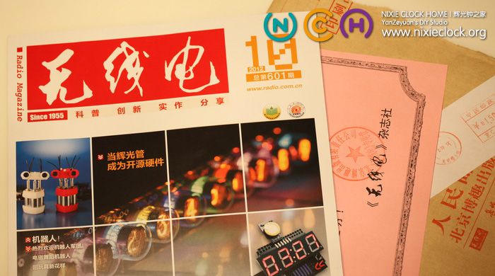
NixieModule登上《无线电》杂志封面…

同许多80后一样,告别纸质媒介已近十年…
回想起大学里必订的4本杂志《无线电》、《电子世界》、《电脑爱好者》、《中学科技》,恐怕现在已经被网络冲击的销量大不如从前;

但作为曾经的《无线电》忠实读者,而且有幸将自己的作品再次刊登在上面,并荣登封面,还是颇有喜悦之感!

这次刊登的作品是QS30-1 Nixie Module for Arduino,与官微宏(Agu’s Mill)一起从硬件设计到Arduino应用均进行了详细的介绍;
其实大部分内容均出自本博客相关的博文,有兴趣的朋友欢迎前去浏览。
在此感谢《无线电》杂志社,感谢各位朋友的关注与支持!

http://i1237.photobucket.com/albums/ff474/yanzeyuan/Nixie%20Module%20for%20Arduino/QS30%20Nixie%20Module%20v101/2012_11_12_IMG_7909.jpg
(更多…)

IN-14(前苏联ИН-14)辉光钟v2版|Nixie Clock【严泽远作品】

我的上一代IN-14辉光钟诞生于3个多月前,延续了QS18-12辉光钟经典的功能和特点,仅仅是和QS18-12黄金纪念版使用了不同的辉光管。
很多朋友在收藏以后,纷纷提出了一些个人想法,经过仔细的斟酌,汇总了一些需求,结合本人的改进思路,IN-14辉光钟v2版由此诞生…

先来SHOW一下IN-14辉光钟v2版:
http://i1237.photobucket.com/albums/ff474/yanzeyuan/IN-14%20Nixie%20Clock%20New/2012_09_24_IMG_7224-.jpg
(更多…)

QS30-1 Nixie Module for Arduino v1.0.1 | 新版辉光管显示模块

QS30-1 Nixie Module for Arduino辉光管模块诞生3个月以来,收到了许许多多国内及国外朋友的E-mail,有赞赏也有建议,更多的是技术交流,在这里对大家的支持表示感谢!

同时,我也收集整理了一下朋友们的建议,结合自己的想法,推出了QS30-1 Nixie Module for Arduino v1.0.1版(与第一版完全兼容,可相互级联使用),这里简单介绍一下:
1、优化了电路设计,提高了升压模块效率;
2、对PCB布局进行了细微调整,简化生产步骤;
3、在面板和背板添加了端口说明文字;

老规矩,先看照片:

http://i1237.photobucket.com/albums/ff474/yanzeyuan/Nixie%20Module%20for%20Arduino/QS30%20Nixie%20Module%20v101/2012_09_11_IMG_6979.jpg

(更多…)

Adapter for QS30-1 Nixie Module | 辉光管显示模块转接板

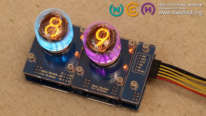
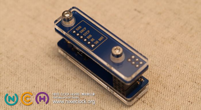
由于QS30-1 Nixie Module采用了级联设计模式,模块与模块之间全部使用的是2×3的排针和排母,包括控制I/O以及电源,所以对于应用来讲,连接电源适配器以及控制I/O没有统一的接口,需要朋友们自己动手制作DC5.5-2.1转杜邦线的电源座,为此,这次特别设计了一款适用于QS30-1 Nixie Module的转接板,见下图:

http://i1237.photobucket.com/albums/ff474/yanzeyuan/Nixie%20Module%20for%20Arduino/QS30%20Nixie%20Module%20v101/2012_09_11_IMG_6997.jpg

转接板可与QS30-1 Nixie Module完美匹配,另外集成了高品质DC5.5-2.1电源插座,和6针I/O接口,12V的电源适配器可以轻松对接级联的Nixie Module。
(更多…)

QS30-1 Nixie Module | 辉光管显示模块 介绍【应用篇】

辉光管显示模块作为一类创意元素,重在应用;而在传统应用方案中,时钟是最经典,也是最实用的一个!
尤其是在有了强大的Arduino类库支持以后,我们可以更加随心所欲的实现自己的应用创意。
为了组合应用,今天准备了一些4联的背板和6联的背板,结合相应的控制程序,做了两款时钟:
1、4位QS30-1辉光钟
2、6位QS30-1辉光钟
具体的实现方法不再赘述,方案颇多,DS1302、DS3231等等等等,尤其是使用该模块以后,每个模块的背景LED颜色都可以单独配置,比起以前我设计的辉光钟来说,又多了很多种玩法,上图先!
六位QS30-1辉光管电子钟:
http://i1237.photobucket.com/albums/ff474/yanzeyuan/Nixie%20Module%20QS30-1/2012_07_21_IMG_6280.jpg

(更多…)

error: Content is protected !!