Omnixie Plus Smart Wifi Clock | Omnixie Plus 智能Wifi辉光钟

在去年三月发布了Omnixie以后,传统辉光钟的定义已被刷新,它不再是一个只是用辉光管来显示数字的普通单一的钟表,而是具有Wifi自动校时、手机智能控制、音乐铃声、四国语言报时等现代功能的智能时钟,且简单大方的纤薄底座,复古的北美黑胡桃边框搭配高光亮边的铝合金拉丝面板,得到了国内外朋友的一致认可。

After the release of Omnixie in March last year, the definition of the traditional Nixie clock has been refreshed. It’s no longer a simple clock that uses Nixie tubes to display number but has Wifi automatic adjusting, mobile phone control, music tones, four-language talking time and some other modern intelligent clock. It has a simple and generous slim base, the black walnut frame with high-bright edge aluminum brushed top plate, widely obtains the customer of the recognition and praise.

但由于尺寸的限制,18mm直径的辉光管并不能完全彰显辉光钟的可贵气质,所以自从Omnixie作品诞生以后,我一直在准备设计一款基于30mm直径的辉光管的Omnixie,最初的想法是除了管子变大以外,其余的尺寸均根据Omnixie的尺寸等比例放大,虽然很有挑战,但经过一年多的设计和开发,终于实现了这个想法,我给她取名为Omnixie Plus。

However, due to the size limitation, the 18mm diameter Nixie tube does not fully reflect the precious of the Nixie clock. Therefore, since the release of Omnixie, I have been preparing to design an Omnixie based on 30mm diameter Nixie tubes. The original idea is remaining dimensions are scaled according to the size of Omnixie. Although it’s very challenging, after more than a year of design and development, I finally realized this idea, I named  it Omnixie Plus.

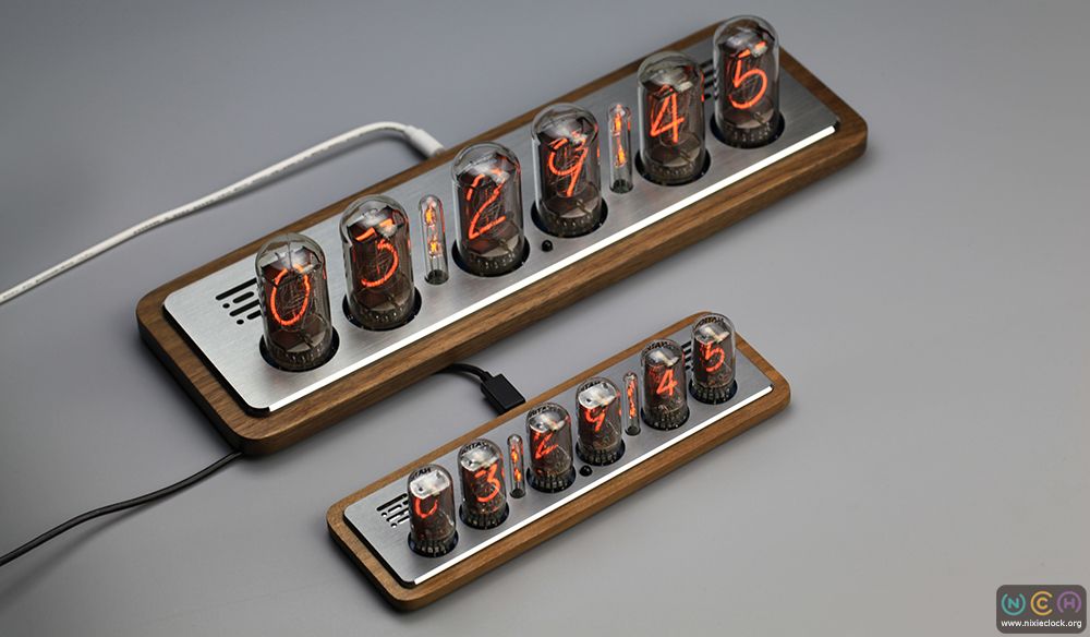
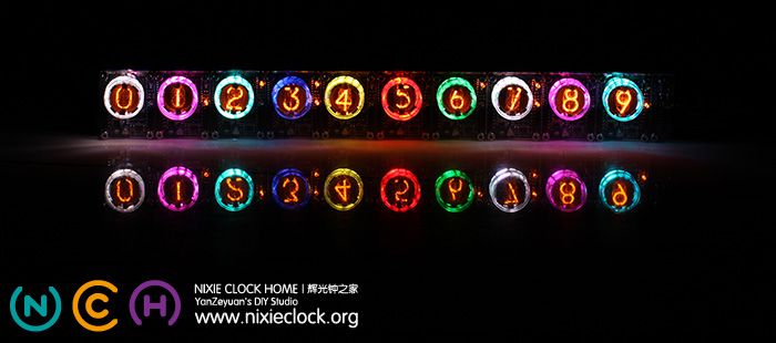
Omnixie Plus在今年5月17日的美国加州湾区的Maker Faire 2019上已经正式发布,在详细介绍之前,我们还是按照惯例先睹为快:

Omnixie Plus has been officially released on 17th May, the Maker Faire 2019 in the Bay Area of California, USA. Show some pictures before we go into detail:

(更多…)

Omnixie Smart Wifi Clock | Omnixie 智能Wifi辉光钟

转眼间,距上一个辉光钟作品诞生已时隔近六年,原以为我已经对古朴而又柔美的辉光管进行了完美的诠释,未曾想时隔近六年后,又一次改变了辉光钟的概念,一款完美的智能Wifi辉光钟作品Omnixie诞生

How time flies, six years have past since my last Nixie clock released, I thought I had performed a perfect interpretation of Nixie Tubes, never thought that I redefined it again after six years, a perfect smart Wifi Nixie Clock released today.

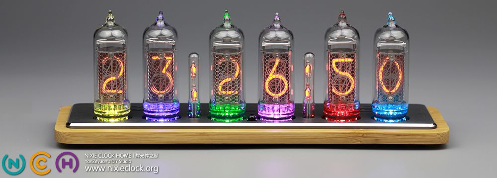
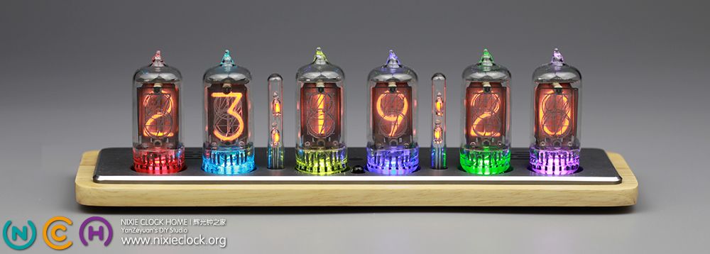
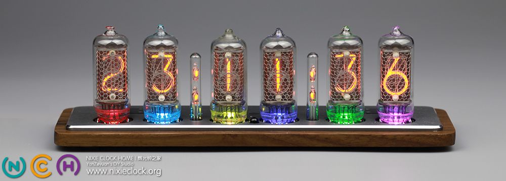
现在看来,之前所做过的辉光管时钟作品包括大多数DIYer的辉光钟作品,都仅仅是将电子时钟里的显示器件这个元素替换成了辉光管,而后或多或少的对外观加以修饰,使其Hold的住辉光管古典的气场,除此之外,所谓的跨越时空的古老器件与现代科技的完美结合并不凸显。所以在3年前萌生新的想法时,许久未能赋予她新的定义。Omnixie从2015年初开始动手做第一版设计,这3年时间里经历了5次改版,每一次改版都源于对极致的苛求,对以前所有创作过程中所遇到的问题进行革新,对时下流行的科技进行整合应用,而又始终不离开时钟这个本质!在详细介绍之前,我们先睹为快:

For now though, all Nixie clocks that have been done before include most of DIYer’s Nixie clocks are merely replaced the element of display components with Nixie tubes, and the appearance was modified to make it more classical. In addition, the perfect combination of the so-called time-spaced ancient devices and modern technology is not highlighted. So when a new idea was created three years ago, it’s hard to give it a new definition. The Omnixie project was launched for the first edition from the beginning of 2015, it has undergone five revisions in the past three years. Each revision has its origins in the rigorous demand and innovates all the problems encountered in the previous creative process, integrated and applied the popular science and modern technology, but never leave the essence of the clock. Before we go into details, let’s look at it first:

(更多…)

QS30-1 Nixie Module for Arduino v2.0.0 | 辉光管显示模块【软件篇】

通过上一篇QS30-1 Nixie Module for Arduino v2.0.0 | 辉光管显示模块【硬件篇】的介绍,相信大家对辉光管显示模块v2.0.0的硬件有了相应了解。
但除了有相应的高压升压电路和逻辑驱动电路以外,还需要软件方面的配合才能让这些模块焕发夺目光彩,完成我们设计的应用。
先来回忆一下那种火红的朦胧:

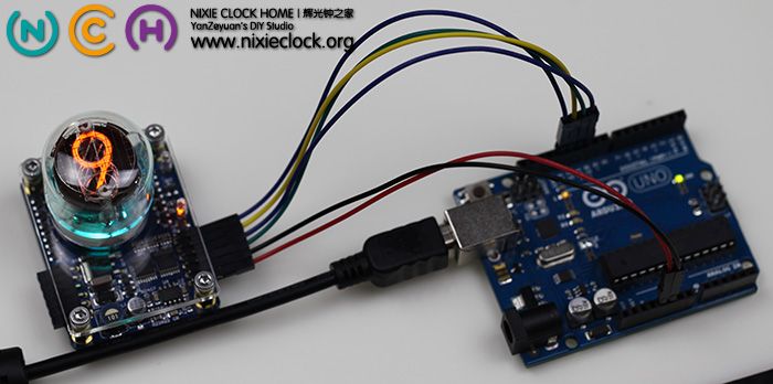
本次新版本的辉光管显示模块,依旧是使用了两片74HC595芯片来实现串行数据通讯控制,对数字、LED颜色以及氖灯的控制实际上都是对74HC595芯片的控制。
在本文中,就以一个C51核心的单片机系统来对驱动软件进行简单的阐述,并给出具体驱动代码。

通过辉光管本身的应用来看,一共有0-9这10个数字要进行控制,另外还有RGB LED三个颜色要进行控制,以及2个氖灯要进行控制,共需要15bit的译码输出,根据原理图,两片74HC595共有16bit输出,对应的控制关系表如下:

(更多…)

QS30-1 Nixie Module for Arduino v2.0.0 | 辉光管显示模块【硬件篇】

辉光数码管|Nixie tube,这种问世于上世纪的古老器件,已经令越来越多的爱好者着迷,相信浏览过我的博客的朋友都无法忘记那特有的显示效果…

由于辉光管的工作原理决定了她必须由170V的高压才能驱动,为了使更多喜爱她的朋友能够使用她来创作,不必去烦恼如何产生高压、如何整理高压逻辑驱动器,一年半之前我开发了QS30-1 Nixie Module v1.0.0,并且受到了很多国内外朋友的喜爱,也因此结识了许多世界各地对开源硬件着迷的朋友,收到他们作品照片的同时,也分享和体验了那份成就感。

更多关于老版本QS30-1 Nixie Module v1.0.0的信息和辉光管的详细介绍请移步:

本次推出的v2.0.0版本的辉光管模块,针对v1.0.1版本进行了一些改进,主要体现在:

  • 改进了升压电路方案,模块驱动电压由原来的12V DC改为5V DC。
  • 采用体积更小集成度更高的逻辑器件,由双层PCB板改为单层PCB板设计。
  • 整体厚度从57mm降低为44mm(含辉光管和陶瓷管座高度)。

(更多…)

红外线遥控器全新升级 | New IR Remote

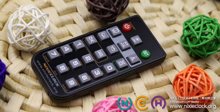
相对于复杂的造型设计,我更追求简约的外形风格,所以,我的时钟作品几乎都采用红外线遥控器来进行控制;例如开关机、查看日期和闹钟以及温度、设置日期时间等等;
之前一直采用时下流行的超薄遥控器,她身材娇小,很薄,21个按键也能够满足需要,但通过这些年的观察发现,超薄薄膜型红外遥控器的寿命比较短,使用时间久了需要用力按压按键才能正常使用。

为此,经过对市场上众多同类产品的对比和筛选,Nixie Clock Home的新款红外线遥控器全新升级!

(更多…)

基于Futaba GP1211AI的VFD点阵动画时钟

声明:本作品的电路设计和软件设计为kazuyuki。
自从白菜VFD 128×64在市场上出现以来,相信有不少朋友都过了把VFD的瘾,尤其是在kazuyuki的带领下一路过来,版本已经升级到了V7。
我也忍不住口水,弄了一套kazuyuki的V7套件,过了把瘾。在此,感谢kazuyuki,感谢所有为玩转128×64付出过的朋友们。
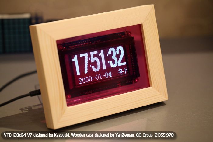
但是外壳的设计和制作一直以来都是DIY的瓶颈,对于V7来讲,一款廉价又实用的外壳显得尤为重要;
今天,终于结束了V7裸奔的日子,经过几番设计,一款成本在15元左右的V7外衣诞生:

(更多…)

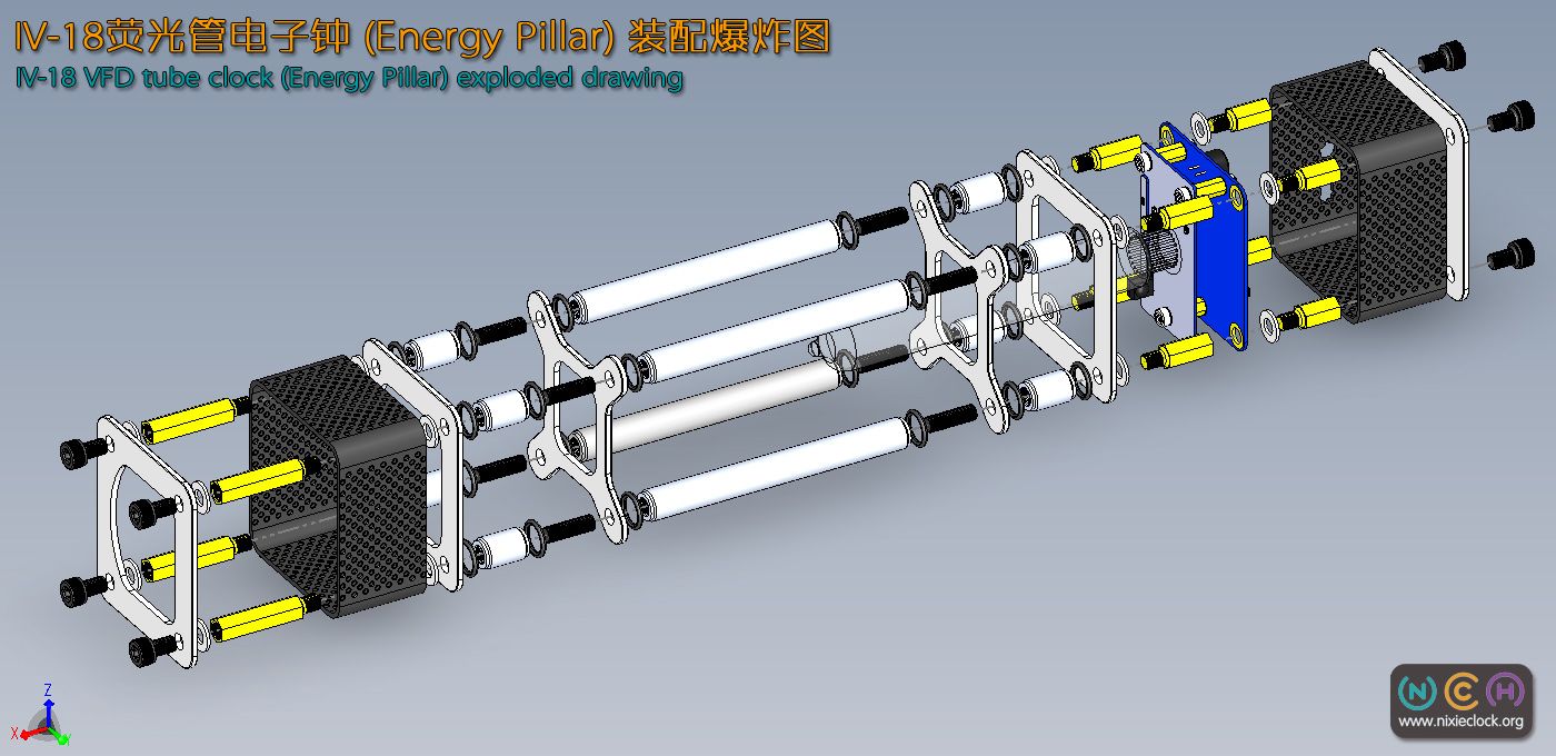
IV-18荧光管电子钟装配指南【IV-18 Energy Pillar Assembly Instructions】

上个月推出了IV-18(ИВ-18)荧光电子管时钟DIY套件,由于外壳装配过程稍稍复杂,所以这两天用Solidworks绘制了一整套3D装配指南图片,供大家参考。
IV-18 (ИВ-18) the VFD tubes Clock DIY kit published last month, the housing assembly process is a little more complicated, so these two days with Solidworks drawn complete set of 3D assembly guide pictures for your reference.

整个外壳的装配过程请按照图示说明进行,如有疑问请大家给我留言!
The housing assembly process is carried out in accordance with the illustration, any questions please leave a message or email me!

此图高分辨率,点击此图可以放大! Click to enlarge!

此图高分辨率,点击此图可以放大! Click to enlarge!

(更多…)

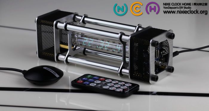
IV-18(前苏联ИВ-18)荧光管电子钟【Energy Pillar.能量柱】【严泽远作品】

一直以来,对金属质感的东西颇有些亲睐,但鉴于DIY金属外壳的难度,自从水晶城堡作品诞生以后,就没有打算在金属外壳设计上再投入大量的时间和精力。直到……

直到遇见IV-18荧光电子数码管以后,又开始了一轮新的折腾……的确,IV-18荧光管独特的外形、通透的管身,冷艳的色彩,让她与金属外壳搭配一定是完美的创作。于是,经过一次又一次的设计、修改、打样,一年多断断续续的制作,又一款电子管时钟作品诞生——Energy Pillar能量柱……


(更多…)

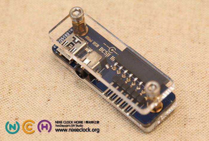
Adapter for IV-22 VFD Module | 荧光管显示模块转接板

IV-22 VFD Module | 荧光管模块 设计之初就考虑到了外接电源与I、O接口的连接问题,同QS30-1辉光管显示模块一样,我也为她设计了专用的Adapter转接板。
原本,模块与模块之间均采用的是单排弯脚的8Pin排针和排母,这些针脚包括所有的控制I/O和电源接口,所以对于应用来讲,要连接电源适配器或者Arduino等控制模块需要朋友们自己动手用杜邦线连接,无法用MiniUSB线直接为模块供电,有了这个转接板,可以方便的使用DC3.5/1.35接口的直流电源或者MiniUSB接口直接为模块供电,见下图:

(更多…)

IV-22 VFD Module for Arduino [hardware design]

VFD tube, vacuum fluorescent display, which was invented in Japan in 1967, typifies the display component of the vacuum electronic era.

Just as the Nixie Tube, VFD tube is also on the verge of extinction. It has been fade out from modern applications since the 1990’s. Young generations may have never seen its limpid cyan fluorescence, given life by the intelligence of the last century.

With the same concept of developing the Nixie Tube module for Arduino, in order to make the VFD tube reborn, combined antiquated electronics with modern technology, the VFD tube module is developed as independent blocks. Without headaches about high-voltage generation, logical driver, soldering, geekers can focus their time and energy on achieving the design idea of the final works. Meanwhile, for designers with no electronic background, Arduino is all they need, of which 4 I/O pins can supply full control on a dozens of VFD tube modules with individual RGB led background lights. Other MCU systems or developer kits would do the same.

Thanks aGuegu for testing my VFD tube moudle first-handed and developmet of its Arduino library.

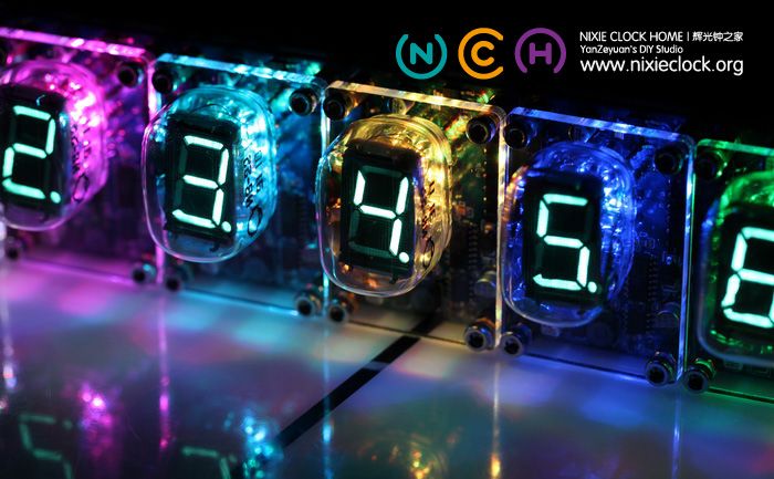
The technology of VFD is still widely used nowadays, however, no more in tubes. VFD screen is Hi-fi equiment, Automobile instrument panels. This device consists of a hot cathode (filaments), anodes (phosphor) and grids encased in a glass envelope under a high vacuum condition. The cathode is made up of fine tungsten wires, coated by alkaline earth metal oxides, which emit electrons when heated by an electric current. These electrons are controlled and diffused by the grids, which are made up of thin metal. If electrons impinge on the phosphor-coated plates, they fluoresce, emitting light. Constract to the Nixie tube, it requires lower supply voltage, which means is safer and longer life expectancy.

This module application use model IV-22 (ИВ-22) VFD tube, dimensioned as a rectangle of 32mm * 22mm. It display on top with 12 pins. These batch of tube were mass manufactured in former Soviet Union during the Cold War, whereas, they are stored in warehouse corners and being forgotten. But its material guarantees its unlimited shelf life.

The specifications of IV-22 VFD tube:
1.  High vacuum inside, unlike the inertia in nixie tube.
2.  Lower vlotage requirement and energy consumption. The filament voltage is between 1.0 and 1.3 volt, working both on DC and AC. The voltage of anodes (phosphor) against grids is 22-30v. The current in filament is 100mA, while 4-10mA in grids.
3.  Seven-segment digital display, can present decimal figures and basic letters.
4.  Cyan colored, bright light with high contrast, visible even in daylight, and not Glare.

Check some photos, and more description comes afterwards.

http://i1237.photobucket.com/albums/ff474/yanzeyuan/Nixie%20Module%20for%20Arduino/IV-22%20VFD%20Module/2012_12_12_IMG_8615.jpg

(更多…)

error: Content is protected !!